Reconstruction Settings
Settings related to the reconstruction process can be found in the Create Model part of the MESH MODEL tab.
Image Depth-map Calculation
The first part of a model calculation is a depth-map calculation for each image. Here, you can set up the parameters of this part. This part of the calculation uses mainly the GPU. Please close all applications that are using GPU in order to lower GPU memory usage.
TIP: You can select images that you do not want to use in a model computation by image multi-selection and the selected inputs' panel (prior to the model computation).
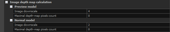
- Preview model These settings are applied just if you use the preview quality model computation.
- Image downscale Images scaled down by this factor are used for the depth map computation instead of the original resolution of images. The higher the number, the faster the computation, but it results in a lower detail. Using number 1 means no change in the scale (100% resolution), using number 2 means that each side of an image will be two times smaller (25% of the original image resolution), etc.
- Maximal depth-map pixel count The maximum depth-map pixel count. This value does not override the Image downscale value; both will be applied and may affect resolution. The default value of 0 means the setting is ignored. To use this setting, ensure you set a high value.
- Normal model These settings are applied just if you select normal quality model computation.
- Image downscale Images scaled down by this factor are used for the depth map computation instead of the original resolution of images. The higher the number, the faster the computation, but it results in a lower detail. Whereas using number 1 means no change in the scale (100% resolution), using number 2 means that each side of an image will be 2 times smaller (25% of the original image resolution), etc.
- Maximal depth-map pixel count The maximum depth-map pixel count. This value does not override the Image downscale value; both will be applied and may affect resolution. The default value of 0 means the setting is ignored. To use this setting, ensure you set a high value.
NOTE: Downscale for depth maps (defined in the 1Ds Selected input(s) panel for selected pictures)
x Image downscale (defined in Reconstruction settings) = resulting downscale for selected images for depth-map computation.
Laser Scans
These settings are used when a laser scan is being used during a model computation.
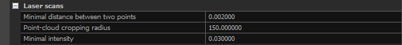
- Minimal distance between two points Use this setting to define the final density of the laser-scan-related parts of the model. However, parts of the model that come from images (photogrammetry) can be denser. Use Mesh calculation / Minimal distance between two vertices to control the overall density of the final model.
- Point-cloud cropping radius Points of a scanner that are further from the scanner position than this value will not be used in the model computation. Use this setting when you know that far points have low accuracy and you do not want to use them in the final model.
- Minimal intensity Use this setting to disable using points with intensity lower than this value. See your scanner specification. Usually, low-intensity points are not accurate enough, and you may not want them to be reconstructed.
Mesh Calculation
Mesh is created after depth maps are calculated. Use these parameters to control the properties of the final mesh.
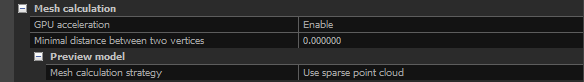
- GPU acceleration Enable this option to speed up the mesh calculation. It is enabled by default.
- Remove marginal triangles Enabling this setting removes marginal triangles, resulting in a non-watertight mesh.
- Minimal distance between two vertices Use this setting to define the final density of a model. WARNING: use this just if you are sure that you know the scale of the model. If your scene is geo-referenced, then this number will be in meters/feet. Do not forget to change it accordingly before another model computation in the next project.
- Preview model These settings apply just if you select the preview quality model computation. The model computed in a preview mode is always singleton, i.e., consists of a single part.
- Mesh Calculation Strategy You can choose to Use sparse point cloud. If you use this setting, then the Image depth map calculation / Preview model / Image downscale and Mesh calculation / Preview model / Max vertices count will not be used and will be hidden as they become irrelevant. Or you can choose Max vertex count. With this option, you can define the maximum number of vertices that the final model can contain. A proper decimation factor is estimated in this case. However, of course, the number of vertices will not be exactly the same as you had selected.
- Max vertex count If the Mesh calculation strategy is set to Max vertex count, then this option is visible. It defines the maximal number of vertices that the final model can contain. A proper decimation factor is estimated in this case. However, of course, the number of vertices will not be exactly the same as you had selected.
Advanced
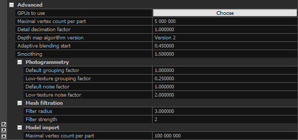
- GPUs to use If you have multiple GPUs in your computer, then you can choose here which one you want to use.
- Maximal vertex count per part Defines the maximal count of vertices in a part. We do not recommend changing this value.
- Detail decimation factor The bigger the value, the lower the detail and the lower the number of triangles in the final model.
- Depth map algorithm version Select the version of the algorithm to use for calculating the depth maps (Version 1 is the legacy algorithm).
- Adaptive blending start Is useful mostly with laser scans and metric data, and it determines the level of detail that is going to be created. The higher the value, the greater the detail. It is not recommended to use a non-default value (0.45).
- Smoothing The Smoothing setting works similarly to the Smoothing Tool. The higher the number, the smoother the model will be.
- Photogrammetry settings
Default grouping factor and Low-texture grouping factor define the final density of mesh vertices.
Default noise factor and Low-texture noise factor define the final smoothness of mesh.- Default grouping factor The default density. If set to 2, then there should be 2x2=4 times less vertices. You can also lose detail when setting it to a higher than the default value. This setting can also be used when images are having a negative impact on the quality of a mesh; when both images and laser scans are being used to mesh, increasing this value will mean the laser scans will be prioritized for meshing.
- Low-texture grouping factor The bigger the value, the lower the density of vertices in the low-textured parts of mesh.
- Default noise factor The bigger noise the factor, the smoother the mesh. You can also lose detail when setting it to a higher value than the default one.
- Low-texture noise factor The bigger value, the smoother the low-textured parts of a mesh.
- Mesh filtration settings
- Filter radius Filter radius is used in depth map calculation. This setting should not be modified.
- Filter strength Filter strength is used in depth map calculation. This setting should not be modified.
- Model import settings
- Maximal vertex count per part Defines the maximal count of vertices in a part for the imported model.