Selected Input
After images or laser scans are imported, it is possible to select them in the list of all inputs on the left side in the view that is set to 1Ds or 2Ds.
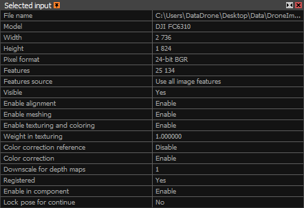
Upon selection, properties of the inputs will be shown in the Selected Input(s) panel.
If inputs are selected after registration (alignment), additional settings are involved in the inputs' properties: Enable in component
and Lock pose for continue.

- File name A name and a location of the selected input file(s).
- Model Make and model of a camera that was used to create the input file(s).
- Width The image width in pixels.
- Height The image height in pixels.
- Pixel format The count of bits per pixel and a specification of the color channel.
- Features The number of features that were detected in this image during the last alignment.
- Features source You can choose more component integration strategies by selecting which features you would like to be included in a new alignment of components (separately for each image in each component).
By choosing a proper strategy you can significantly reduce the amount of RAM required during the alignment.
Merge using overlaps uses only the components' images/points which are in common, that are overlapping images. This strategy reduces the computation time and memory consumption.
Use component features uses only the points used in the alignment of the imported component. This option is the fastest and most beneficial with RAM shortage.
Use all image features will use all images/points. The slowest process with the highest memory requirements.
- Visible Enable or disable the visibility of a camera cone for the selected input in the 3D view.
- Enable alignment Set this option to Enable if you want to include the selected input(s) in the registration process and further processing. Otherwise choose the option Disable.
- Enable meshing Set this option to Enable if you want to include the selected input(s) in the model computation/meshing. Otherwise choose the option Disable. This function applies to all components.
- Enable texturing and coloring Set this option to Enable if you want to include the selected input(s) in the texture or coloring calculation of a model. Otherwise choose the option Disable.
- Weight in texturing Set the weight of the selected input(s) that is going to be taken into consideration during the texturing or coloring processes. Set the value lower than 1 to decrease the impact
of the selected input(s) in the coloring/texturing process.
- Color correction reference Set this option to Enable if you want to use this input as an etalon during the color correction calculation. Otherwise choose the option Disable.
Colors of this input will not be changed if this option is enabled.
- Color correction Set this option to Enable if you want to include this input in the color correction calculation. Otherwise choose the option Disable to skip this image
(e.g. images with structured light (projected pattern) used only for geometry).
- Downscale for depth maps Set the image downscale factor for the depth map computation. The higher the integer, the faster the computation, but it results in a lower detail.
Using integer 1 means no change in the scale (100% resolution), using integer 2 means each side of the image will be twice as small (25% of the original image resolution), etc.
Please note the final downscale for depth map computation is calculated as follows:
Downscale for depth maps (defined in the 1Ds Selected input(s) panel for selected pictures) x
Image downscale (defined in the Reconstruction settings)
- Registered Indicates whether the input is registered in the selected component or not.
- Enable in component Set this option to Enable if you want to include the selected input(s) in the reconstruction and further processes under the selected component.
Otherwise choose the option Disable. This function applies only to the selected component unlike the option Enable alignment.
- Lock pose for continue Lock the relative positions of the selected cameras in the selected component for further processing. This option can be useful if you process images in batches.
Align the first set of images, fine-tune the component, lock positions for cameras in the component, add another set of images and align again. This way camera positions cannot be changed
(e.g. the component cannot be split).
Image layers
Images can be organized into layers for different processing steps, like masking unwanted parts or using specific images for texturing. Properly named images are loaded together, with layers automatically assigned based on image or folder names.
- [Type] layer Image layer assigned to the input. The [Type] label changes according to the layer type, so an input can have multiple layer entries.
- Enable masks for alignment Enable the mask image layer for use in the alignment process.
- Enable masks for meshing Enable the mask image layer for use in the meshing process.
- Enable masks for texturing and coloring Enable the mask image layer for use in coloring and texturing processes.
Camera Priors
Priors are properties (camera/scene information) known before alignment. They may be used to influence the quality of alignment. They can be fixed, approximate or completely unknown.
Pose, calibration and lens distortion Priors can all be set when selecting a single image, or more, in the selection panel. When selecting a laser scan input (known for its internal format .lsp), only pose Priors are displayed in the panel.
Prior Pose
The following parameters define what we know about a certain camera position:

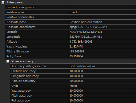
- Locked pose group If you type in a positive integer, a group will be set. Leave this field blank or type in a negative integer in order to ungroup poses.
- Relative pose - type of Prior Position for the inputs. It defines relative position between cameras and can be set to:
Unknown - the relative position between cameras is not defined
Draft - the relative position between cameras is known to some level of precision and can be optimized during alignment
Exact - the relative position between cameras is known and will not be altered during the alignment
- Relative coordinates Defines a coordinate system for the relative positions among cameras in a pre-calibrated component. This option is visible only for the inputs that are connected
in a rig (e.g. individual .lsp files in one laser-scanner position, or images with exact or locked XMP files).
- Absolute pose - type of Prior Position for the inputs. It defines the global camera positions (relative to the system in which cameras are located, not between cameras) and can be set to:
Unknown - the Prior Position for the inputs is not defined
Position - the camera position is known to some level of precision and can be optimized during alignment
Position and orientation - both approximate position and orientation of a camera are known but can be optimized during alignment
Locked - No changes in camera position and orientation allowed during alignment
- Absolute coordinate Defines a coordinate system of the prior coordinates. The type of coordinates under this setting depends on the selected coordinate system.
- Latitude/X,Y,Z... Depending on the selected coordinate system, you will be able to define ground-control-point physical coordinates in angular or cartesian coordinates.
- Yaw/Heading, Pitch/Elevation, Roll/Bank Rotation angles of a camera around Y, X, Z axis, respectively.
- Pose accuracy defines the accuracy of the camera location. It can be set to the global settings or to custom values. If the Accuracy settings source
is set to Global camera prior settings, the values set in the Alignment settings are going to be taken. When Accuracy settings source is set
to Edit custom values, it is possible to manually change the accuracies of the selected input(s).
Prior Calibration
The following parameters provide you with the information on internal camera calibration priors (focal point, projection center and so on):
Prior Lens Distortion
Define information about your optics:
By default, the lens distortion model is set to No lens distortion with prior set to Approximate.
This means that RC tries to find a solution where lens distortion is as close to zero as possible.
This is not realistic if images suffer from a visible lens aberration. In such case, you should either define proper distortion coefficients or set the lens prior to Unknown.
Rigging
Rigging parameters are applicable only for inputs connected in a rig (e.g. individual .lsp files in one laser-scanner position).
Rig ID Type of a rig, e.g. laser-scan point clouds.
Prior An identifier of a rig instance at a certain position. All 6 .lsp files for one laser-scanner position will share the same number.
Model A camera index within a rig (e.g. index of an .lsp file in one laser-scanner position (0-5)).
Camera After Registration
These are properties (camera/scene information) known after alignment. They define the quality and resulting parameters after alignment:
Relative position uncertainty
Information about the uncertainty in the position of a camera relative to other cameras registered in the component.
Registration Calibration
Here you will find the final calibration parameters (applicable for this input only in the selected component) calculated in the alignment process.
Registration Lens Distortion
Here you will find the resulting lens distortion parameters calculated during alignment (applicable for this input only in the selected component).
Sub-select Images
It is possible to select only registered images or only unregistered images. Make sure that all images are selected beforehand.


