Managing Ortho Projections
Managing orthographic projections is particularly useful when importing a model into a new project. Color layer and digital surface model with depth, and altitude layer are stored with each ortho projection. Alternatively, you can also render digital terrain model with depth and altitude layers. This tutorial will show you how to display, process and export them into different formats.
Prerequisites
You must have an ortho projection created. Click here to learn how to create an ortho projection.
Displaying an Ortho Projection
Ortho projections can be displayed in the 2D view. Go to the 1Ds view in the left panel and find the ortho projection that you want to display. It is located under the component that was used to create a model from which the ortho projection was rendered. Now CLICK on the chosen ortho projection and DRAG AND DROP it into a 2D view.
When an ortho projection is displayed in the 2D view, the ORTHO 2D context tab shows up in the application ribbon. In the ORTHO 2D/VIEW tab you can choose which layer you want to display in the Source part. This way you can see how the exported ortho projection is going to look. You can also change which objects can be seen on the ortho projection. To access tools which can be used on the ortho projection, export an ortho projection or objects created on it go to the ORTHO 2D/TOOLS tab.

If your projection is georeferenced, you can DRAG AND DROP it into the map view to see its geo location and whether it is correctly located. For more information on the map view click here.
You can also sample an ortho projection into a regular grid using the Sample Points tool in the Tools part of the ORTHO 2D/TOOLS tab. You can learn more about the Sample Points tool here.
Batch Processing
It is also possible to batch-process multiple orthographic projections. This is for the execution of multiple orthographic projections simultaneously.
- Select the model for which you want to create an orthographic projection in the 1Ds panel.
- Set the reconstruction region. More about reconstruction regions can be found here.
- Click the Ortho Projection tool to activate it(F11).
- Click on the preferred side of the reconstruction region (use gray squares in the sides' corners to define upper left corner of the ortho projection) onto which the model is going to be reprojected. Use the Estimate button to define the optimal size (resolution) of the ortho projection or edit those values manually. Click on the Add to batch button (an unprocessed ortho projection will appear under the model in the 1Ds panel project tree). Repeat until you define as many orthographic views as you need.
- Select the unprocessed ortho projections in the 1Ds panel.
- Finally, click the Render button in the Selected ortho photo(s) panel to automatically process all unprocessed ortho projections added into the batch.
- The processed projections will be added to the project tree, under the unprocessed ones.
- To delete all unprocessed ortho projections, first select the ortho projections in the 1Ds panel and then click the Delete button in the Selected ortho photo(s) panel.
Measures
Within your orthographic projections, you can measure distances and control surfaces and volumes.
You can find information for the surfaces, and volumes of the selected ortho projection in the Selected ortho photo(s) panel:
- Cut volume - The volume between the bottom side of the reconstruction region and the visible surface of the rendered model.
- Fill volume - The volume between the top side of the reconstruction region and the visible surface of the rendered model.
- Area 2D - Area of the rendered projection, or the area of the top/bottom side of the reconstruction region.
- Area 3D - Area of the visible surface of the rendered model.
In the ORTHO 2D/TOOLS context tab, you can find the Measure Distance tool. This tool can be used to measure both 2D and 3D distances between two points represented by endpoints of the displayed line segment.
- CLICK the Measure Distance button in the Tools panel of the ORTHO 2D/TOOLS context tab.
- The Measure Distance tool is displayed in all ortho 2D views.
- Use your mouse to MOVE the tool line end points.
When you hover your mouse over an ortho displayed in the 2D view, you can also see GPS coordinates and the coordinate system for each point your mouse points at.
Export
You can export selected ortho projection(s) as Ortho Photo, Digital Surface model, or Digital Terrain Model. These three options vary in the information they provide,
so select the preferred option for your purposes.
If multiple ortho projections are selected, then all selected ortho projections are exported.
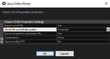
To export an ortho projection go to WORKFLOW tab or the ORTHO context tab. Select an option, into which an ortho projection(s) can be exported. A dialog box for saving a file will pop up. Enter the file name and specify a desired file format. Then Click Save. After you click the Save button, the Export dialog box will appear:
Export Ortho Photo

- Export world file Select to also export the world file.
- World file coordinate system Select from these: Projected, Global or Image. With Projected, the model is projected on a
selected plane defined via the reconstruction box. This can be useful when making turned elevations. If you are to create a map or a top view, select Global.
Select Image, when you want to create elevations or sections.
NOTE: A world file is a plain text computer data file used by many geographic information systems (GIS) to geo-reference raster map images. Small-scale rectangular raster image maps can have an associated world file for GIS map software that describes the location, scale and rotation of the map.
- Export projection parameters file Choose to export a file containing projection parameters such as transformation matrices among ortho image, global coordinate system, and world coordinate system, the box definition, image resolution, coordinate system definition etc.
- Compression You can select an algorithm to compress your ortho projection and use a much more compact data representation.
- Export as BigTIFF If your ortho projection is bigger than 4GB, you can export it as a BigTIFF. This option is available when .tif or .tiff format is selected.
- Tile image format Pyramid image file format. Available with .KML and .KMZ formats.
- Tile image resolution (pixel) Pyramid image resolution. Available with .KML and .KMZ formats.
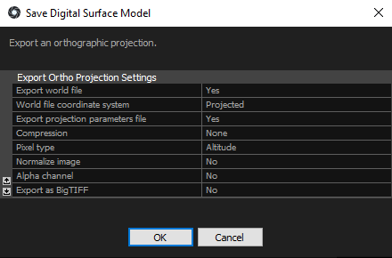
Export Digital Surface Model and Digital Terrain Model
The export of the Digital Surface Model and Digital Terrain Model uses the same settings as the Ortho Photo export, with additional options outlined below.

- Color palette Choose the pallete in which the depth and elevation data will be rendered.
- Color depth Choose between 8-bit and 16-bit depth.
- Pixel type Determine which information is going to be displayed in your export. Altitude shows heights in RealityCapture’s coordinate system, or in the project’s coordinate system, if your model is georeferenced. Depth (local) consists of depths measured from the top side of the reconstruction region. Depth (global) are depths measured from the plane containing the zero point of the project’s coordinate system and is parallel to the projection plane. This way it is possible to create several projections with depths connected to the same plane under one condition, and for projection planes, of all projections, to be parallel. Please note that depths will be exported in a JET color scale for RGB file formats. If you want to export depths as a float, choose the .tiff file format.
- Normalize image This setting enables you to use an exported ortho projection in any of the various image editing software. When this option is set to Yes, heights are normalized in an interval <0,1>. If you wish to preserve depth (global), always set this option to No.
- Alpha channel If this setting is set to Yes, an exported ortho projection will be in the RGBA color model and the background will be transparent. If you decide not to use this setting, your export will be in grayscale. Please note that the final file size might be four times larger when set to Yes.