Georeferencing a Scene
Georeferencing is a process of assigning real-world coordinates to a virtual 3D scene and placing it into a preferred coordinate system. The coordinates are usually acquired using a global navigation satellite system (GNSS) device, and they can be imported and used in RealityCapture in a few different ways. They can be assigned to a specific identifiable place in a scene using ground control points or directly to the camera using the camera priors, flight logs, or XMP files.
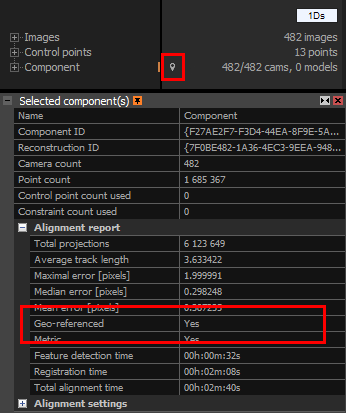
You can see if your scene (component) is georeferenced in the Selected component(s) panel, which appears after selecting a component in the 1Ds view. You can also look for the marker icon next to the component's name.
Ground Control Points
Ground control points (GCPs) allow assigning 3D coordinates in an arbitrary coordinate system to any 2D image point. You can define the scene's origin with a single ground control point. With two ground control points, you can define the origin and the scale. With three or more points, you can define the whole scene and its orientation. Each point should have at least two images (measurements) assigned, but having at least three is recommended. Confirming every suggested image for the assignment to a ground control point is not necessary.
It is recommended to add control points and ground control points before the alignment, even though having a point cloud is helpful in finding the corresponding points in images.
Ground control points, if added before the alignment, become visible in the 3Ds view once the camera poses are known (after the alignment) and at least two images (measurements) are assigned to them. The orange lines, going out of the ground control points, will also become visible. Those represent the residual errors - a difference between the initial (prior) and registered position. The shorter the line, the closer it is to the initial position. Please note that a zero error is unlikely, as the real measurement always suffers from some systematic deviation. The residual lines can also be seen in the 2D view. You turn the visibility of residual errors on or off in the 2D and 3Ds views by checking or unchecking the check box in the view context ribbon (IMAGE 2D / VIEW or SCENE 3D / VIEW).
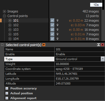
You can also place the ground control points in the map view. First, you need to have control points that are set to a Tie point type. Then activate the Control Points tool and select a control point you want to use as a Ground control point. In the map view, click on a location where you want that ground control point to be placed. The selected control point will instantly change into a Ground control point. The coordinates will be taken from the map. However, all heights will be set to a default value of 1. If you want to change the placement of a ground control point in the map view, change it to a Tie point type and repeat the process.
Control Points
How to add ground control points into your project
Camera Pose Templates
How to export and import camera poses' template
See also:
- How to import ground control points click here.
- How to import a flight log click here.
- Read more about coordinate systems click here.
- Learn how to create and export orthographic projections click here.