Map Wizard
RealityCapture Map Wizard is basically your personal virtual assistant guiding you through a creation of geo-referenced maps and/or models but mainly doing almost all of the defined processing for you.
The whole process is very intuitive and easy. You can call it any time, by clicking the button
in the WORKFLOW tab. There is no necessity to follow it from scratch, you can also leave the guide at any stage and continue on your own, feel free to jump back in, too.
Standard Workflow
-
Starting with a new empty project, clicking on the button, you will be first asked to add some inputs to process:
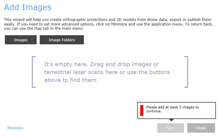
- Via the button, you can insert individual images or an entire image list into the project.
- Via the button, you can add all images in a selected folder with an additional option to include its subfolders.
After importing all images, you will see a count of geo-referenced images, non-georeferenced ones, and a count of images whose sensor is currently not in the camera database. By default, images are grouped with respect to the EXIF data (more information here).
-
If your images do not contain GPS positions in EXIF, you will need to geo-reference your scene using a flight log or some ground control points (coordinates and measurements):
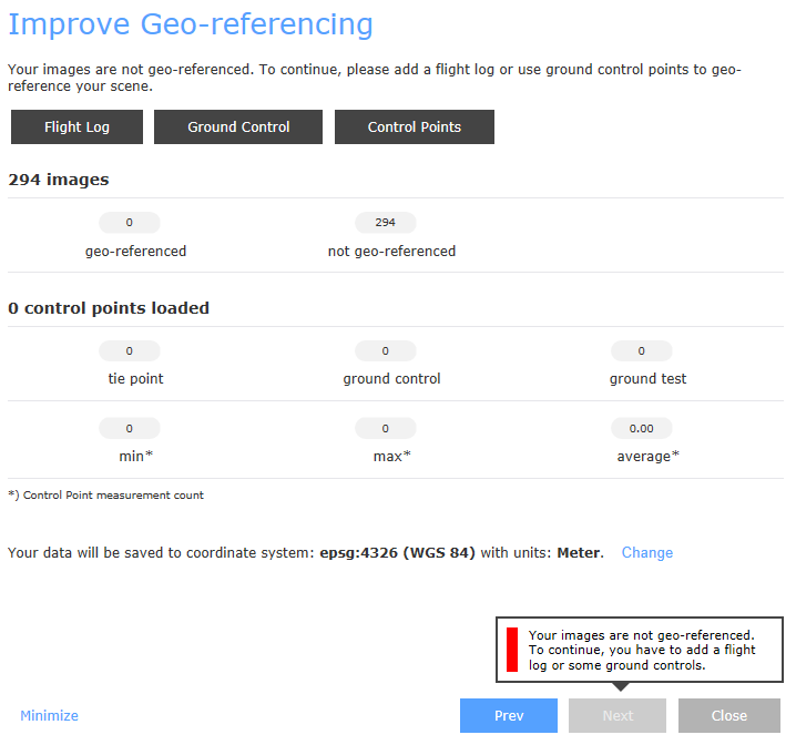
- Via the , you can import a file with camera positions in a specified coordinate system.
- Via the , you can import coordinates of ground control points (GCPs) in a specified coordinate system.
- Via the button, you can import image measurements for (G)CPs.
NOTE: Pay attention to choosing the proper file format and coordinate system of the imported files. In order to use GCPs for geo-referencing, you need to either load the GCP measurements in several images, or minimize the Map Wizard dialog and add the measurements manually.
Also note that, when using both camera priors in the WGS84 coordinate system (GPS) from images as well as GCPs in a different coordinate system at the same time, you need to make sure that you use the same vertical coordinate system. When using both camera priors and GCPs, RealityCapture considers both sets of coordinates. In most cases, GPS coordinates from camera priors are less precise than coordinates of the GCPs, and using both sets can lead to larger errors. -
As soon as you successfully load all inputs, you can proceed to displaying them in the map and to defining an area of reconstruction. In the Verify Reconstruction Region dialog, all your inputs with the real-life coordinates are displayed on the basis of (the world) OpenStreetMap:
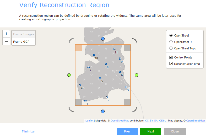
- You can define the reconstruction area with the reconstruction region widget, similar to the one used in the application itself (more info). You can change the horizontal size of the region by dragging the circular widgets and its rotation by dragging the arc widgets.
- The orange square defines the upper-left corner of the orthographic projection to be created. You can change it to another one by clicking on a different corner square.
- To zoom in/out the map, use the mouse wheel or the buttons.
- Use this button to fit the reconstruction area into the middle of the window.
-
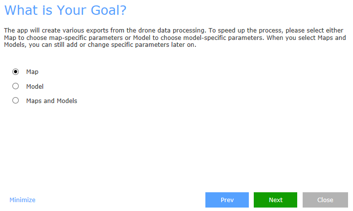
As the next step, you will define your preferred output of the reconstruction. In case it is just a georeferenced orthographic projection, choose Map, and proceed to defining the final quality of the created map. If you wish to create only a 3D textured model, choose the Model option and continue with defining the parameters of the reconstruction. You can also opt for the combination of the two.
Map-specific Parameters
There are two approaches to defining the final resolution (ground sample distance) of your map:
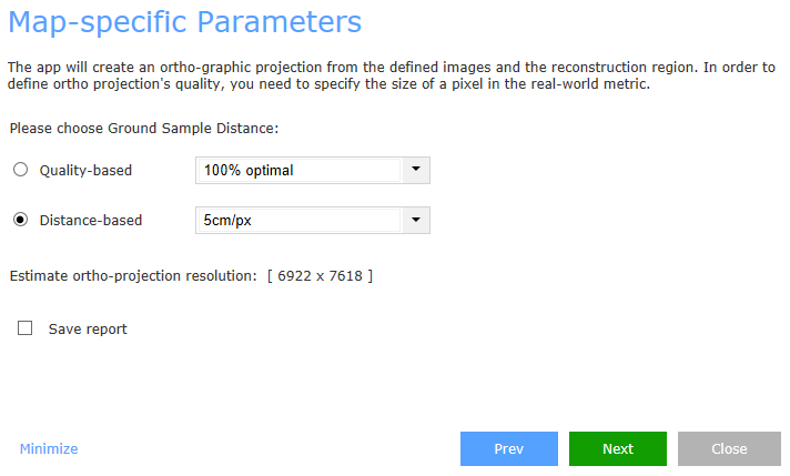
- Quality-based The optimal resolution of an orthographic projection is calculated according to the model quality and created texture. Here you can define the final resolution as a percentage of the calculated optimal resolution. You can either choose from the available drop-down options (100/50%) or enter a value of your own (in %).
- Distance-based Here you can define a desired resolution of your map by defining the pixel size in a real-world metric. Choose from the drop-down menu (1/5/10/50 cm/px) or enter another value corresponding to the unit cm/px.
You can also have a report exported into an HTML file by ticking Save report and choosing a pre-defined report template. Click here for more information on RealityCapture reports.
Model-specific Parameters
In this window, a detail of the created 3D mesh and the texture are defined:
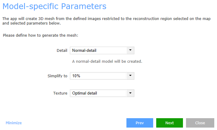
For Detail, you can choose from these pre-defined modes:
- Preview mode creates mesh very quickly but with a low detail. Only tie points computed in the alignment step are used in the mesh calculation.
- Fast normal-detail creates lower quality mesh. Images are downscaled by factor 4 during the depth map computation.
- Normal detail creates a mesh with reasonable quality. Images are downscaled by factor 2 during the depth map computation.
- High-detail mode creates the mesh with highest possible detail but the computation might take longer. Images are not scaled down in this case.
Simplify to You can choose a level of mesh simplification from the drop-down menu (small - 100,000 triangles (tris), medium - 500,000 tris, moderate - 1 million tris, large - 10 million tris, 10/50/100%), or enter your target triangle count or a target percentage of triangles (do not forget to include the % symbol in the second case).
Texture Here you define the quality of the texture created for a simplified model:
- Optimal detail The optimal texel size is calculated and used for creation of texture with 100% quality. The maximal texture resolution is set to 2048x2048.
- 50% quality 2x optimal texel size is used to create texture with 50% quality. The maximal texture resolution is set to 2048x2048.
- 10% quality 10x optimal texel size is used to create texture with 10% quality. The maximal texture resolution is set to 2048x2048.
- 4K The texel size is adjusted in order to create a single texture with 4096x4096 resolution.
- 8K The texel size is adjusted in order to create one texture with 8192x8192 resolution.
- Do not create texture With this options set, the texture is not calculated.
- You can also enter a custom texel size in cm/px. The maximal texture resolution is then set to 2048x2048.
-
The Summary and Fine-tuning dialog provides you with a summary of the selected outputs and lets you perform their final adjustments:
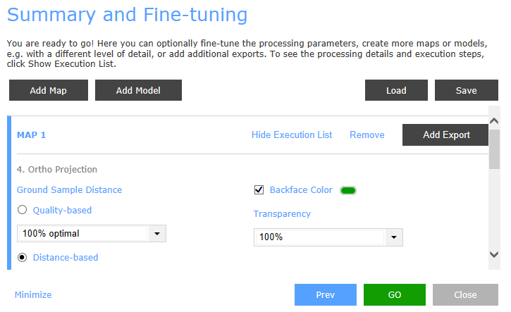
- You may add new outputs by clicking the or buttons. For each of them you can display the selected parameters via button and then change their parameters if required. To remove an item, click in the respective line.
- For each output you can also create a list of exports from the drop-down menu using the button. A map is exportable as an orthographic projection, and digital surface model. Both map and model can be output also as a mesh, uploaded to Sketchfab or Cesium ion, and come with a report.
- The whole configuration can be saved into a file and reloaded via the and buttons.
- Pressing the button will start up the defined processes. You will be able to follow the calculation progress, estimated time of its completion, as well as the current and finished processing steps.
- Once the calculation is finished, you can close the Map Wizard and check your outputs in the 1Ds panel.